The Bigger the Better

“The bigger the better”, a direct quote from our very own rocket man -Dave Cutting.  Of course we agreed with him at the time, but it could as easily be used in our defence, should we hear of Barra Best describing showers of apocalyptic fire balls and rocket shaped metal on his next weather forecast.  Not a scenario that we intend on having to plan for just yet.  The prototype rocket project is merely a concept design which we will use for architectural discovery and will remain safely on Belfast’s terra firma.

Image result for apocalypse weather forecast

I say, “build”.  You say, “how high?”

Of course there are going to be a rocket-load of estimations that we will have to establish – even at this early stage in our project.  

However – ‘team talk’ breakthroughs of:
I say “build”
You say “how high”

are NOT quite the accuracy we are looking for in answering the question of rocket size!  So lets get some numbers…

Early discourse from the engine team indicated they were aiming for a single cylindrical engine of approximately 100 mm in diameter.  Leaving room for engine mounting, and considering what aluminium tubing was available, we settled on a fuselage width of 150 mm and 5mm wall thickness.  This leaves plenty of room to squeeze in the escape pods!

Death Star v1


This beauty will stand a mighty 4m tall from base to nose tip and currently has three divisions.  One for the engine, one for payloads and electronics modules, and a third for the parachute.

3D Printing Our Own Lucky Fin

Something that we will need to test in the future – once we know more about the speed which our rocket may have to cope with – is the aerodynamic properties of the fins.  And of course, it would be a missed opportunity were we not to use this as an excuse to throw something in the Engineering departments wind tunnel to see what happens. Unfortunately the wind tunnel will not be big enough to fit a full size fin inside, therefore a scaled down version needs manufactured.  Lucky enough, there are a number of 3D printers available in the EEECS Maker Space for us to print a model.
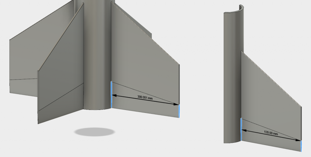
3D printers are not massive, in fact the ones we have can only print in a space of 300 mm^2.  This means the model needs scaled down significantly and only one fin can be printed. This reduction in size poses a worry for the integrity of the entire fin, being only 5 mm at its thickest part at full size.  The biggest we could print was at a 2:5 scale, making the fin at its thickest part 2 mm. The thinnest part at the tail of the fin struggled to touch the ground so a raft was designed into the print.
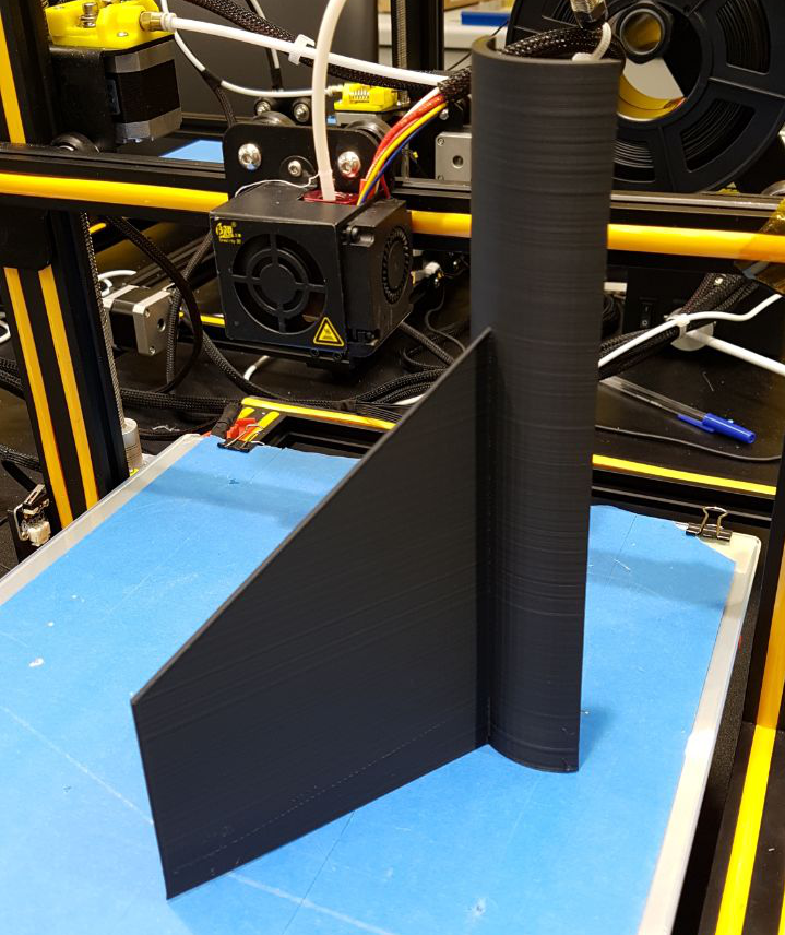
6 – 8 hours later we have our print.  The overall form of the print was good.  The fin itself was strong enough to hold to the fuselage section but because of the size reduction, the accuracy of the fin profile was somewhat affected.  Either way, the fin still needed sanded down before it may be useful in the wind tunnel. This is done by hand with both 800 and 1200 grain sandpaper.
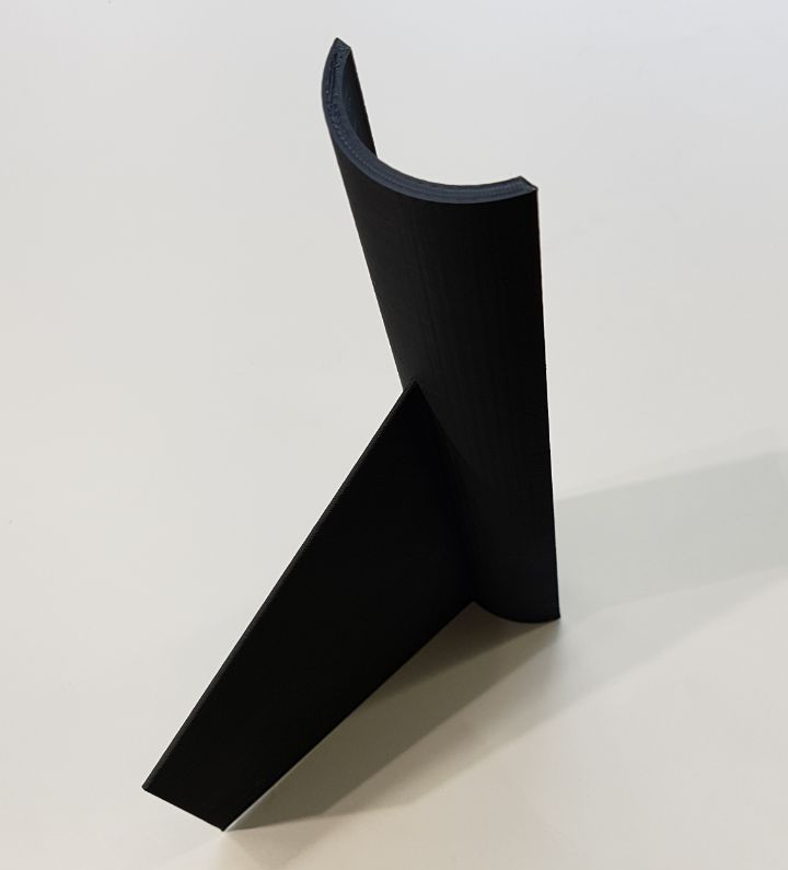
And there we have it!  Ready for the wind tunnel.


Written by Josh Kelso @scottkelso07

Balloon 1: Up, up, up, and… away (23rd May 2018)

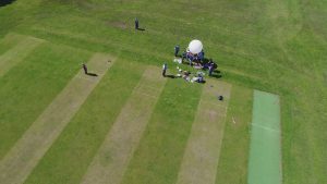
On 23rd May we launched our first high altitude balloon (HAB) from Lurgan. Following a very hectic few days and many late nights the weather and drift predictions were good and we were go for launch and headed to Lurgan Park.

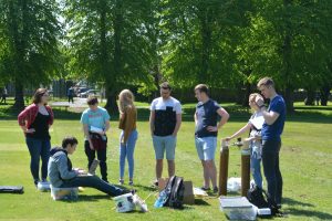
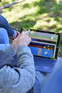
After the payload was tested and packed final radio tests took place and some training on how to use the radio equipment. We had three chase cars in place – two to leave immediately and one to remain behind to feed telemetry until the launch was high enough for local radio amateurs to track.

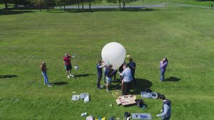
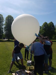
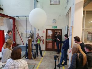
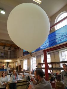
After a few false starts and back-and-forth we began inflation.

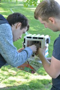
Inflation went fairly well though there was some leaks where we were fitting different diameter pipes together. Given the relatively low pressures though it could be largely removed by gripping the junction as hard as possible. The most difficult bit was trying to hang the payload and extra weight (once removed = lift) off the bottom and judge it well. But the balloon soon filled up! Once we had inflated to the correct (we hoped!) amount it was time for release.

The balloon climbed away nicely and we were immediately getting good data back over both radio links. Chase cars away and the base car remained on station uploading data as received. Fairly shortly other radio receivers started reception as well and pictures began to upload to habhub.

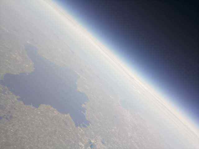
After initially tracking north almost up to Lough Neagh as it climbed the drift swung South-West again. Images sent back included this of Lough Neagh.

Everything was fine until 16km at which point radio data was lost on both channels. We were still seeing a transmission on the frequency but this was a single peaked carrier wave only. The assumption is that the Pi (running both transmissions) crashed but the transmitters remained powered, hence the signal but no data.

Undeterred the chase cars headed onwards trying to track the signal. An hour and a half after data had stopped transmitting the signal was lost entirely. All three cars worked around the area but failed to pick up a definite signal though some possibilities of a signal were found, but not strong enough to be confirmed. As of this time Balloon 1 is lost somewhere in a couple of hundred square miles around an axis from Enniskillen to Fivemiletown and Carrickroe. The hope is that someone will find the payload with the contact cards and get in touch.

Flight History

  • 1511 Liftoff
  • 1519 At 2km being widely tracked
  • 1615 At 16km loss of data
  • 1714 Burst (we have this from radio amateurs who, listening to the waveform, can detect when the burst causes the transmitted to tumble) – the estimated altitude was 30.1km
  • 1747 Loss of signal from Phil’s fixed radio receiver (below horizon)
  • 1749 Loss of signal from Andrew’s mobile radio receiver (below horizon)
  • 1750-1754 Touchdown

This would give a ascent time of 2h2m to ~30km which was similar to predictions given gas volume and a descent time of ~50 minutes.

Lessons Learnt

  • Pis can crash and a single point of failure for tracking is a bad idea where it can be avoided whatever the tracking system
  • Ballooning is cool and we get good feeds and data
  • The setup took far longer than expected (was our first time) – but we could streamline by pre-packing radio sets for cars etc
  • The filling was a bit chaotic and Heath-Robinson to say the least – needs to be thought through more clearly
  • Gas was lost during the filling – junctions need to be remade to be gas tight


Radio Testing

Following a 1am finish the balloon team were back on hand Monday afternoon for some radio distance tests.

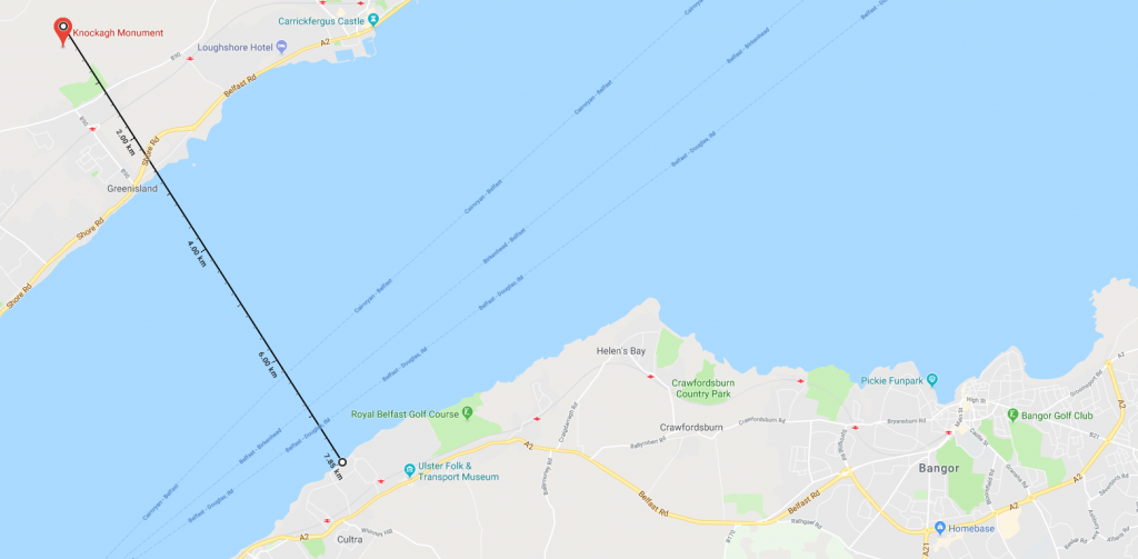
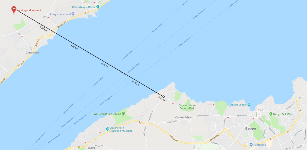
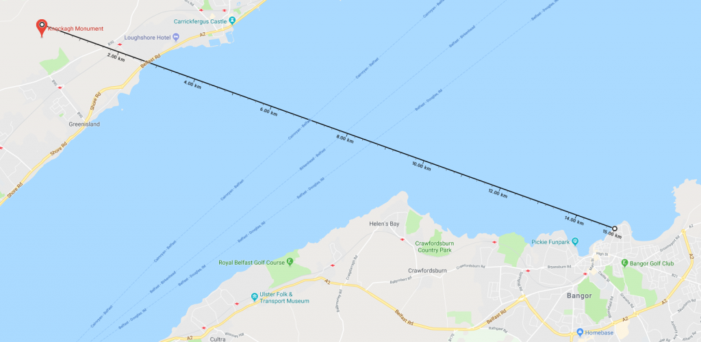
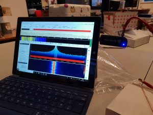
The transmission team went up to the Knockagh Moument which gives a commanding view over Belfast Lough while the receiving team travelled out on the other side. This was a test of both our payload radio systems and our ground two-way PMR radios.

First trial was to Cultra, about five miles.

Following a successful test here the receiver team moves to Helen’s Bay (six miles from the monument).

And following success there into Bangor (10 miles) which is about as far as we could get line of sight for.

Tests were hugely successful if not a bit cold.

Thanks to someone flying a drone nearby we also got some great aerial footage of our testing in progress!

All in all a very successful day, proving the wiring done the night before and some useful learning points using the software.


Radio Assembly

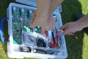
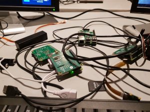
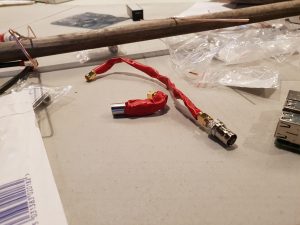
For the balloon project we’ve been busy assembling all the parts together and testing. This led to a frenetic late night session at the marvellous Farset Labs where we were soldering and wiring until 2am.

Hybrid Rocket Engine design version 1

Over the past week the engine team have been preparing designs for the hybrid rocket engine, the aim is to see if we can produce a net thrust from the engine. Different engine designs have been researched to find the most simple and most effective design.

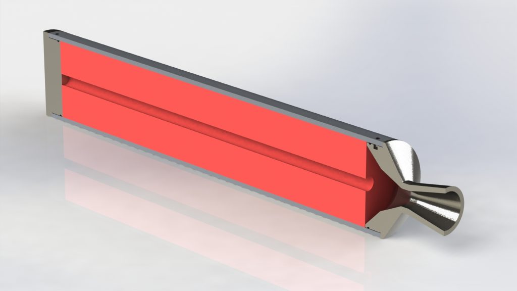
We settled upon a cylindrical aluminium core to house the solid fuel with a chamber to allow the liquid fuel to flow. Attached to either end of the core is an end cap with an injector assembly and a nozzle to direct the expelled gases, both of which are interchangeable to allow for the test of various designs.

Initial engine deisgn

We also decided on materials for the nozzle and end cap, due to the higher temperatures they will be exposed to, they have to be made from a material with a higher melting point. Steel has been proposed for initial testing as it is cheaper than other materials and SHOULD withstand the heat and stresses subjected on it. For the actual engine, it would have a layer of graphite on the inside of the nozzle to withstand the stresses for a longer period of time.